

How To Fix Security Camera Latency Over Lan Cable
How to wire your own ethernet cables and connectors.
What Y'all Need:
Required:- Ethernet Cablevision - bulk Category (True cat) 5, 5e, 6, 6a or college ethernet cablevision
- Wire Cutters - to cut and strip the ethernet cable if necessary
- For Patch Cables:
- 8P8C Modular Connector Plugs ("RJ45")
- Modular Connector Crimper ("RJ45")
- For Fixed Wiring:
- 8P8C Modular Connector Jacks ("RJ45")
- 110 Dial Down Tool
- Wire Stripper
- Cablevision Tester
About the Cablevision:
You lot tin discover bulk supplies of ethernet cable at many computer stores or about electric or habitation centers. You want UTP (Unshielded Twisted Pair) ethernet cablevision of at least Category 5 (Cat 5). True cat v is required for basic 10/100 functionality, you will want Cat 5e for gigabit (1000BaseT) operation and True cat 6 or college gives you a measure of future proofing. You tin also use STP (Shielded Twisted Pair) for actress resistance to external interference only I won't embrace shielded connectors. Bulk ethernet cable comes in many types, in that location are 2 basic categories, solid and braided stranded cable. Stranded ethernet cable tends to work meliorate in patch applications for desktop apply. It is more flexible and resilient than solid ethernet cablevision and easier to work with, but really meant for shorter lengths. Solid ethernet cablevision is meant for longer runs in a fixed position. Plenum rated ethernet cable must be used whenever the cable travels through an air circulation space. For example, above a false ceiling or beneath a raised floor. It may be hard or incommunicable to tell from the package or labeling what type of ethernet cable it is, and so peal out an end and investigate.
Here is what the internals of the ethernet cable wait similar:
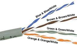
Internal Cablevision Structure and Color Coding
Inside the ethernet cable, there are eight color coded wires. These wires are twisted into 4 pairs of wires, each pair has a common color theme. I wire in the pair being a solid or primarily solid colored wire and the other being a primarily white wire with a colored stripe (Sometimes ethernet cables won't accept whatsoever color on the striped wire, the only way to tell which is which is to check which wire it is twisted around). Examples of the naming schemes used are: Orange (alternatively Orange/White) for the solid colored wire and White/Orange for the striped cable. The twists are extremely important. They are there to counteract dissonance and interference. It is important to wire co-ordinate to a standard to get proper functioning from the ethernet cable. The TIA/EIA-568-A specifies ii wiring standards for an eight-position modular connector such equally RJ45. The two wiring standards, T568A and T568B vary only in the arrangement of the colored pairs. Tom writes to say "...sources suggest using T568A cabling since T568B is the AT&T standard, simply the U.s. Regime specifies T568A since it matches USOC cabling for pairs one & 2, which allows it to work for 1/2 line phones...". Your choice might be adamant by the demand to match existing wiring, jacks or personal preference, merely you should maintain consistency. I've shown both below for straight through cabling and merely T568B for crossover cabling.
About Modular Connector Plugs and Jacks:
The 8P8C modular connectors for Ethernet are oftentimes chosen RJ45 due to their physical resemblance. The plug is an 8-position modular connector that looks like a large telephone plug. At that place are a couple variations available. The primary variation you demand to pay attention to is whether the connector is intended for braided or solid wire. For braided/stranded wires, the connector has sharp pointed contacts that actually pierce the wire. For solid wires, the connector has fingers which cutting through the insulation and make contact with the wire by grasping information technology from both sides. The connector is the weak signal in an ethernet cable, choosing the wrong i volition oft cause grief afterwards. If yous just walk into a reckoner store, it's most impossible to tell what type of plug it is. You lot may exist able to determine what type it is by crimping 1 without a cable.
Modular connector jacks come in a variety styles intended for several dissimilar mounting options. The choice is one of requirements and preference. Jacks are designed to work simply with solid ethernet cablevision. Most jacks come labeled with color coded wiring diagrams for either T568A, T568B or both. Make sure you finish up with the right ane.
Here is a wiring diagram and pin out:
Modular Connector Plug and Jack Pin Out
Ethernet Cable Pivot Outs:
There are two bones ethernet cable pin outs. A straight through ethernet cable, which is used to connect to a hub or switch, and a crossover ethernet cable used to operate in a peer-to-peer fashion without a hub/switch. Generally all fixed wiring should be run equally straight through. Some ethernet interfaces can cross and un-cross a cable automatically as needed, a handy feature.
Standard, Straight-Through Wiring Diagram(both ends are the same):
| RJ45 Pin # | Wire Color (T568A) | Wire Diagram (T568A) | 10Base-T Signal 100Base-TX Point | 1000Base-T Signal |
|---|---|---|---|---|
| 1 | White/Light-green | | Transmit+ | BI_DA+ |
| two | Green | | Transmit- | BI_DA- |
| 3 | White/Orangish | | Receive+ | BI_DB+ |
| 4 | Blue | | Unused | BI_DC+ |
| 5 | White/Blue | | Unused | BI_DC- |
| half-dozen | Orangish | | Receive- | BI_DB- |
| 7 | White/Brown | | Unused | BI_DD+ |
| eight | Brown | | Unused | BI_DD- |
Straight-Through Ethernet Cablevision Pin Out for T568A
| RJ45 Pin # | Wire Color (T568B) | Wire Diagram (T568B) | 10Base-T Signal 100Base-TX Betoken | 1000Base-T Betoken |
|---|---|---|---|---|
| 1 | White/Orangish | | Transmit+ | BI_DA+ |
| 2 | Orangish | | Transmit- | BI_DA- |
| 3 | White/Greenish | | Receive+ | BI_DB+ |
| 4 | Blue | | Unused | BI_DC+ |
| five | White/Blue | | Unused | BI_DC- |
| 6 | Green | | Receive- | BI_DB- |
| 7 | White/Dark-brown | | Unused | BI_DD+ |
| eight | Brown | | Unused | BI_DD- |
Straight-Through Ethernet Cable Pivot Out for T568B
Crossover Cable Wiring Diagram:
| RJ45 Pivot # (END ane) | Wire Color | Diagram End #1 | RJ45 Pin # (END 2) | Wire Color | Diagram End #2 |
|---|---|---|---|---|---|
| 1 | White/Orange | | one | White/Green | |
| two | Orange | | ii | Green | |
| 3 | White/Green | | iii | White/Orange | |
| iv | Blue | | 4 | White/Brown | |
| 5 | White/Blue | | 5 | Chocolate-brown | |
| 6 | Dark-green | | 6 | Orange | |
| 7 | White/Brown | | 7 | Blue | |
| 8 | Brownish | | 8 | White/Blue | |
Crossover Ethernet Cable Pin Outs
+Note: The crossover ethernet cable layout is suitable for 1000Base-T operation, all four pairs are crossed.
How to wire Ethernet Patch Cables:
- Strip off about two inches of the ethernet cable sheath.
- Untwist the pairs - don't untwist them across what yous have exposed, the more untwisted cable you accept the worse the problems you can run into.
- Align the colored wires according to the wiring diagrams higher up.
- Trim all the wires to the same length, about 1/two" to 3/4" left exposed from the sheath.
- Insert the wires into the RJ45 plug - make sure each wire is fully inserted to the front of the RJ45 plug and in the right guild. The sheath of the ethernet cablevision should extend into the plug by well-nigh ane/ii" and will be held in place by the crimp.
- Crimp the RJ45 plug with the crimper tool.
- Verify the wires ended upwardly the right gild and that the wires extend to the front of the RJ45 plug and make skillful contact with the metal contacts in the RJ45 plug
- Cutting the ethernet cablevision to length - make sure it is more than than long enough for your needs.
- Repeat the above steps for the second RJ45 plug.
How to wire fixed Ethernet Cables:
- Run the full length of ethernet cable in place, from endpoint to endpoint, making sure to leave excess.
- At 1 end, cut the wire to length leaving enough length to work, but non as well much backlog.
- Strip off nigh 2 inches of the ethernet cable sheath.
- Align each of the colored wires according to the layout of the jack.
- Use the punch downwards tool to insert each wire into the jack.
- Repeat the to a higher place steps for the second RJ45 jack.
If an ethernet cablevision tester is available, use it to verify the proper connectivity of the cablevision. That should be it, if your ethernet cable doesn't turn out, expect closely at each stop and see if you can find the problem. Often a wire ended upward in the wrong place or ane of the wires is making no contact or poor contact. Also double bank check the color coding to verify it is correct. If you see a mistake or problem, cutting the finish off and outset again. A ethernet cablevision tester is invaluable at identifying and highlighting these issues.
When sizing ethernet cables retrieve that an finish to end connection should not extend more than than 100m (~328ft). Try to minimize the ethernet cable length, the longer the cable becomes, the more it may affect performance. This is unremarkably noticeable as a gradual subtract in speed and increment in latency.
Notes:
Power over Ethernet (PoE):
Power over Ethernet has been implemented in many variations before IEEE standardized 802.3af. IEEE 802.3af specifies the ability to supply an endpoint device with 48V DC at up 350mA or approximately 16.8W. IEEE 802.3at updates the PoE standard to supply upwards to 600mA or approximately 28.8W, it is often known as PoE+. The power is delivered using two pairs in the ethernet cable. The device must exist capable of receiving power on either the data pairs [Mode A] (often called phantom ability) or the unused pairs in 100Base-TX [Mode B]. IEEE 802.3bt farther updates the PoE standard to use all four pairs of the cable to deliver up to 90W of power. PoE tin be used with any ethernet configuration, including 10Base-T, 100Base-TX or 1000Base-T. Power is simply supplied when a valid PoE endpoint is detected by using a low voltage probe to expect for the PoE signature on the endpoint. PoE power is typically supplied in ane of ii ways, either the host ethernet switch provides the power, or a "midspan" device is plugged in between the switch and endpoints and supplies the power. No special cabling is required.
| RJ45 Pin # | Wire Color (T568A) | Wire Diagram (T568A) | 10Base-T Point 100Base-TX Signal | PoE |
|---|---|---|---|---|
| i | White/Green | | Transmit+ | Manner A + |
| 2 | Dark-green | | Transmit- | Mode A + |
| iii | White/Orangish | | Receive+ | Mode A - |
| 4 | Blueish | | Unused | Style B + |
| 5 | White/Blue | | Unused | Mode B + |
| 6 | Orange | | Receive- | Mode A - |
| 7 | White/Brown | | Unused | Mode B - |
| eight | Brown | | Unused | Style B - |
Ability over Ethernet Power Commitment
Protocol Details:
| Protocol | Standard | Symbol Encoding | Symbol Rate (Mbaud) | Data Encoding | Information Bits per Symbol | Pairs per Channel | Pairs Used | Nyquist Frequency Bandwidth (MHz) | Minimum Cablevision Category |
|---|---|---|---|---|---|---|---|---|---|
| 10Base-T | IEEE 802.3i | Manchester | 10 | None | 1 | 1 | 2 | ten | iii |
| 100Base-TX | IEEE 802.3u | MLT-3 | 125 | 4B5B | 4/v | 1 | ii | 62.5 | v |
| 1000Base-T | IEEE 802.3ab | 4D-PAM5 | 125 | None | ii | iv | 4 | 62.5 | 5e (v)one |
| 2.5GBase-T | IEEE 802.3bz | DSQ128 (second-PAM16) | 200 | LDPC(1723,2048), 64B/65B, CRC8 | three.125 | 4 | iv | 100 | 5e2 |
| 5GBase-T | IEEE 802.3bz | DSQ128 (second-PAM16) | 400 | LDPC(1723,2048), 64B/65B, CRC8 | 3.125 | 4 | 4 | 200 | half-dozen (5e)2 |
| 10GBase-T | IEEE 802.3an | DSQ128 (2D-PAM16) | 800 | LDPC(1723,2048), 64B/65B, CRC8 | 3.125 | four | 4 | 400 | 6a (6)iii |
| 25GBase-T | IEEE 802.3bq | DSQ128 (second-PAM16) | 2000 | LDPC(1723,2048), 64B/65B, CRC8 | iii.125 | 4 | four | k | 84 |
| 40GBase-T | IEEE 802.3bq | DSQ128 (2d-PAM16) | 3200 | LDPC(1723,2048), 64B/65B, CRC8 | 3.125 | 4 | 4 | 1600 | 8four |
Data Rate = Symbol Rate ten Data Bits per Symbol x Pairs per Channel
The combination of the Symbol Encoding and Data Encoding determines how many Data Bits per Symbol at that place are.
1. Designed to work on most Cat 5 ethernet cable, Cat 5e specifications ensure 1000Base-T performance.
2. Although designed for Cat 5e/half-dozen, non all cabling will be usable at the full range, especially for 5GBase-T on Cat 5e.
3. Reduced range when used with Cat half dozen (55m), Cat 6a supports the full 100m range. Some True cat 5e may back up operation at reduced altitude.
iv. 30m range.
Cable Category Details:
| Cable Category | Rated Nyquist Frequency Bandwidth (MHz) | Common Uses |
|---|---|---|
| 1 | None | Telephone Wiring |
| two | ane | Telephone Wiring |
| iii | 16 | Telephone Wiring, 10Base-T |
| 4 | 20 | Token-Ring, 10Base-T |
| five | 100 | 100Base-TX, 10Base-T |
| 5e | 100 | 1000Base-T, 100Base-TX |
| 6 | 250 | 1000Base-T, 100Base-TX |
| 6a | 500 | 10GBase-T |
| 71 | 600 | >10GBase-T |
| 7ai | m | >10GBase-T |
| 8 | 2000 | 25GBase-T, 40GBase-T |
Increasing category levels are backward compatible.
Manufacturers volition often test and certify their ethernet cablevision well beyond the standards.
one. Category seven/7a specification wiring does not utilise RJ45 connectors.
Related Reading Material

Source: https://www.ertyu.org/steven_nikkel/ethernetcables.html
Posted by: jamescithys.blogspot.com
0 Response to "How To Fix Security Camera Latency Over Lan Cable"
Post a Comment