

How To Splice The Wires For A Security Camera
How to splice the wires for a security camera
Security cameras need ii types of cables to operate, a power supply cablevision and a video cable. Wireless security cameras exercise non require a video cable but they do crave the power supply cable. The power cablevision transports 12V DC, low-voltage ability from the transformer, which is plugged into an 110VAC power outlet, to the camera. This cable has two 18 estimate wires, a positive wire and a negative wire, both inside a single jacket. The negative wire volition be marked with a black or white stripe. The video cablevision is a RG-59: coaxial cable which is shielded and requires BNC connectors to protect the integrity of the video signal beingness carried.
- Security cameras demand two types of cables to operate, a power supply cablevision and a video cablevision.
- The video cable is a RG-59: coaxial cable which is shielded and requires BNC connectors to protect the integrity of the video betoken being carried.
Use your knife or cablevision cutters to split the 2 insulated wires autonomously approximately iii inches from the cut cease of the cable, leaving the installation intact on both wires. You tin can usually pull these autonomously with your easily. Do this on both ends which you intend to splice together. You should now accept two power cables, with two insulated wires coming out of each for a total of four wires to exist spliced.
Remove one-half an inch of the insulation from the end of each of these iv wires.
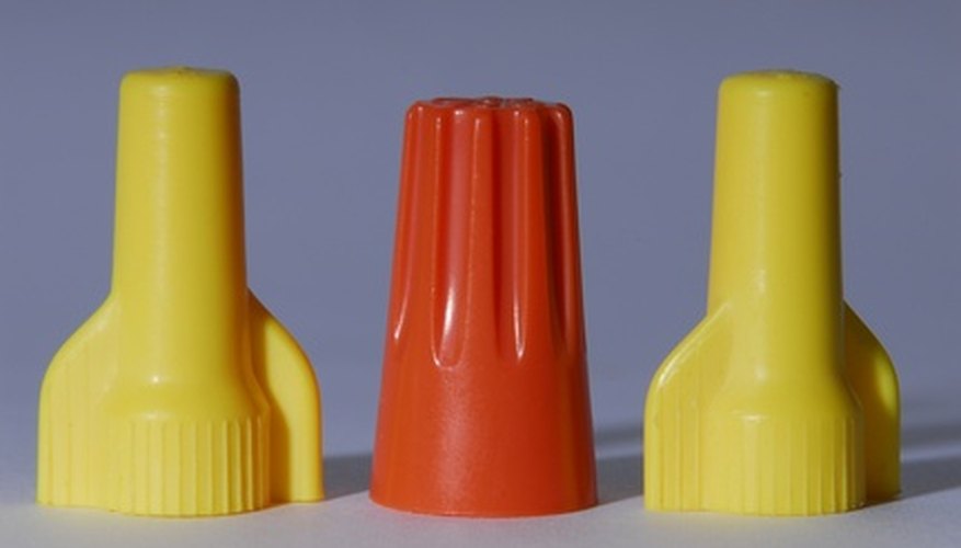
Splice these two power cables together, using wire nuts, by twisting the exposed copper ends together making sure that you twist positive from one cable to the positive from the other cable and the negative wire, or striped wire, from one cable to the negative wire, or striped wire, from the other cable. Screw a wire nut on to the joined or twisted together positive wires and a 2nd wire nut on the twisted together negative wires. Lay the wire basics against the cablevision and wrap everything with insulated electricians tape.
Splice these two power cables together, using Barrel connectors, by preparing the cables only like you did for the wire nut splice, just without twisting them together. Insert the exposed copper wire from the positive conductor into ane terminate of the butt connector and crimp that end of the connector downward. Insert the other positive wire into the other cease of the same barrel connector and crimp it down. Do the aforementioned for the two negative wires using a second Barrel connector. Wrap everything with insulated electricians tape.
- Remove one-half an inch of the insulation from the stop of each of these iv wires.
- Insert the other positive wire into the other end of the same butt connector and crimp it down.
Await at the cut end of the RG-59 cablevision and you lot will meet iv separate parts which make up this cable. In the centre is the copper heart conductor wire. Surrounding the heart usher wire is a polyurethane white insulator. Next is the aluminium or copper braid. And finally, at that place is the outer jacket of the cable. As you prepare this cablevision for the BNC connector is important that y'all prepare each of these four separate parts independently of each other. The copper centre conductor must remain untouched by the braid.
- Expect at the cut stop of the RG-59 cablevision and you volition see four dissever parts which make up this cable.
- In the centre is the copper centre conductor wire.
Take the BNC crimping tube and hold information technology aslope the finish of the RG 59 cable to mensurate your first cut. The crimping tube will have a larger diameter part and a smaller diameter role. The larger diameter function is the end of the crimping tube that you want to match confronting the end of the RG-59 cable.
- Take the BNC crimping tube and hold it alongside the end of the RG 59 cable to measure your get-go cutting.
- The larger bore role is the end of the crimping tube that yous want to lucifer against the cease of the RG-59 cable.
Marker, or just eyeball, the outer jacket on the cable where the big part of the crimping tube ends and the smaller part begins. This will be about 3/8 or one/2 inch from the stop of the cable. This measurement depends on the length of the large part of the crimping tube which you have purchased with the BNC connector.
Cut and remove the outer jacket simply by ringing it with a pocket knife or using cable cutters. Be very careful non to damage the aluminium braid which is right underneath the outer jacket.
Unravel the exposed aluminium braid so you can pull it away from the polyurethane insulation effectually the copper centre conductor.
Cut and remove the polyurethane insulation from the copper centre conductor. You tin band it with a pocketknife or use cable cutters and it should pull gratuitous towards the cut end of the centre usher. The cable is now ready for the connector and the cablevision should now have only the copper center usher exposed and the aluminium complect pulled back over the outer jacket.
- Unravel the exposed aluminium braid so you can pull it away from the polyurethane insulation around the copper centre conductor.
- The cable is now ready for the connector and the cable should now take only the copper centre conductor exposed and the aluminium complect pulled back over the outer jacket.
Slide the crimp tube over the cable with the minor terminate going on the cable first. Before you lot can slide the crimp tube on you lot must pull the aluminium braid towards the cut end of the cablevision and so the crimp tube can go around it and slide directly onto the outer jacket of the cablevision.
Slide the BNC connector into place, pocket-sized finish first, with the copper centre conductor and the polyurethane insulation going within of the modest role of the connector and the aluminium braid and outer jacket staying on the outside of the minor part of the connector. As yous push the connector down into the cable it will pull the aluminium complect downward within the outer jacket at the same time. Looking inside the connector and make sure that none of the aluminium complect has inadvertently remained within the connector and possibly touching the centre conductor. If the aluminium complect is touching the eye conductor the connection will not work.
Slide the crimping tube support the outer jacket until it is touching the BNC connector. Use your crimping tool to now crimp the larger portion of the crimping tube and complete the compression placement of the BNC connector.
Repeat this process, placing the 2d BNC connector on the second piece of cable. When y'all accept completed this you lot should have two pieces of video cable with a BNC connector on each piece. Apply the BNC butt connector to connect these BNC connectors together. The video cable splice is now consummate.

Source: http://www.ehow.co.uk/how_7740979_splice-wires-security-camera.html
Posted by: jamescithys.blogspot.com
0 Response to "How To Splice The Wires For A Security Camera"
Post a Comment